If you want to know what the menu options do, or how to hack your badge, you are in the right place. Thanks to SeeEss for the original DC23 shoot badge which this badge is heavily based upon, particularly the firmware.
The menu is brought up by pressing SELECT (right button) in most modes.
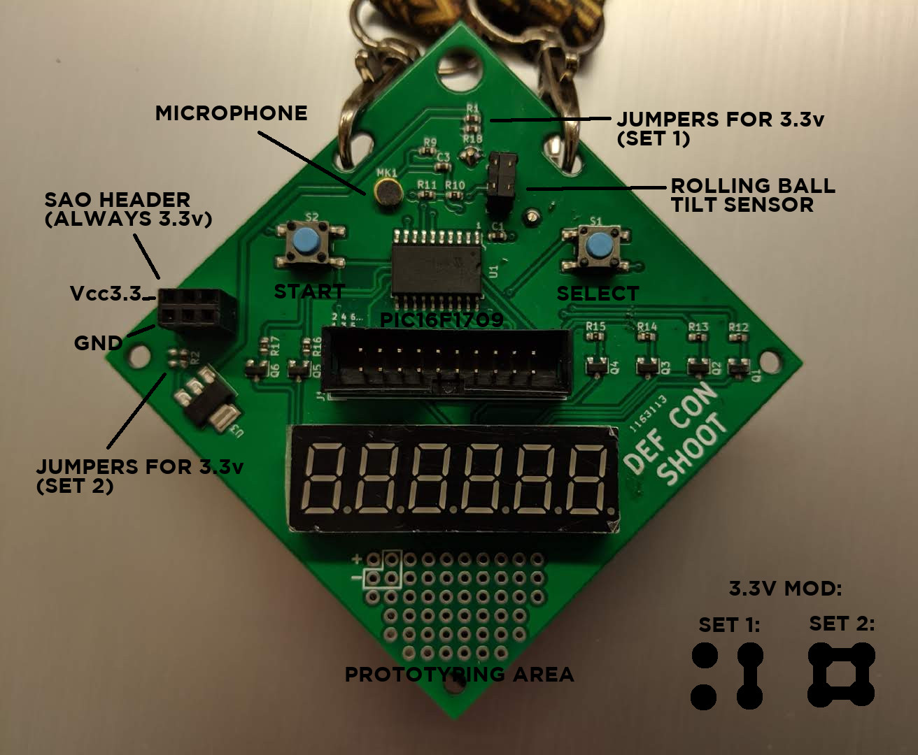
If you'd like to run the entire board off 3.3v, two sets of jumpers must be reconfigured. Set 1 in the picture above must have the horizontal jumpers removed and the left vertical side jumpered. Set 2 can be bridged completely 4-ways with a single ball of solder. This will run the entire board off the 3.3v regulator that otherwise is only used for the Shitty-Add-On header. The board normally runs off unregulated power in the as-shipped configuration.
A prototyping area is provided near the bottom of the board. These pads are connected in a "stripboard" configuration, except for the Vcc and GND pads, which are arranged in a way that a second linear regulator could be installed, if desired. After removing the battery holder, the configuration of the pads should become more obvious.
| Connector J3 Pin Num | PIC16F1709 Pin Num | Pin Description | Signal Name | Pickit3 Pinout |
| Pin 1 | Pin 4 | RA3 | Start Btn | CS/Tx |
| Pin 2 | Pin 5 | RC5 | Segment E | |
| Pin 3 | Pin 6 | RC4 | Segment D | |
| Pin 4 | Pin 7 | RC3 | Segment C | |
| Pin 5 | Pin 8 | RC6 | Segment F | |
| Pin 6 | Pin 9 | RC7 | Segment G | |
| Pin 7 | Pin 10 | RB7 | Digit 4 | |
| Pin 8 | Pin 11 | RB6 | Digit 3 | |
| Pin 9 | Pin 1 | VDD | VDD_VBAT | +V |
| Pin 10 | Pin 20 | VSS | GND | GND |
| Pin 11 | Pin 12 | RB5 | Digit 2 | |
| Pin 12 | Pin 13 | RB4 | Digit 1 | |
| Pin 13 | Pin 14 | RC2 | Segment B | |
| Pin 14 | Pin 15 | RC1 | Segment A | |
| Pin 15 | Pin 16 | RC0 | Segmnt DP | |
| Pin 16 | Pin 17 | RA2 | Tilt Sensor | |
| Pin 17 | Pin 18 | RA1 | Mic | SCL/SCK |
| Pin 18 | Pin 19 | RA0 | Select Btn | SDA/SDI |
| Pin 19 | Pin 2 | RA5 | Digit 6 | |
| Pin 20 | Pin 3 | RA4 | Digit 5 |
The firmware is largely the same as the DEF CON 23 electronic shoot badge, and the 23 firmware should run unmodified. You will, however, need a hacked version of XPLAB or the commercial version, in order to enable optimizations, otherwise it will not fit on the chip.
The DEF CON 23 shoot badge firmware can be found on SeeEss' Github Project